ford ballast resistor wiring diagram
IF USING HEI USE 12 GAUGE AND NO BALLAST RESISTOR. RT DOOR CB BLOWER 40A Blower Motor LBEC 2 50A LOCKS Fuse.
Pertronix Resistor Wire Vintage Mustang Forums
The Ford N-series tractors were a line of farm tractors produced by Ford between 1939 and 1952 spanning the 9N 2N and 8N modelsThe 9N was the first American-made production-model tractor to incorporate Harry Fergusons three-point hitch system a design still used on most modern tractors today.
. Start date May 17 2005. Fuel Rail Kit - Complete. 13 pin Euro plug wiring diagram.
Such coil has very low resistance of around 05 to maybe 15 Ohmsas aftermarket coils entered picture and the. This means that if the ignitor has a fault it will not operate at all. Dyna S Ignition System is a complete self-contained electronic ignition system built with the latest state-of-the-art engineering.
Terminator X for Ford Part 2. I have a 2012 Ford Focus. After getting gas and.
If you use a ballast resistor connect to 12 volt side of ballast resistor. STUD 1 40A Trailer Wiring Automatic Level Control ALC Compressor Relay MBEC 1 50A SEAT CB. We think you will find when you have these breaking up problems low voltage is the culprit.
Sphynx cat breeders near lalmonirhat 6 volt relay on genset. Double-check those circuits including wiring harness and connectors. EWD Chrysler Voyager from 1983.
Thermoswitch parked car heater 73. 50 bmg wood stock. DDM Fuse PDM Fuse ECC Fuse AUX PWR 2 Fuse STUD 2 30A Trailer Wiring ABS 60A Electronic Brake Control Module EBCM.
COIL hot side of the coil thru a ballast resistor 12V to 6V ST to the starter solenoid. Troubleshooting tips for your pertronix ignitor and coil installation. The ballast resistor or resistance wire can be on either side of the.
29112021 indak ignition switch. Diesel Fuel Injector Driver Module Resistor 1 Diesel Fuel Injector Installation Kit 2 Diesel Fuel Pin 1 Dimmer Switch 1. I have read a few places that it is possible to use a Ford TFI distributor by modifying the shutter wheel to have 8 equally sized shutters and adjusting the pickup location to match.
7 pin S type plug and socket wiring diagram. This power supply circuit diagram is ideal for an average current requirement of 1Amp. Light switch wiring diagram depicted here shows the power.
1940 to 1955 ford trucks for sale near Ekibastuz. 12 Volt To 6 Volt Resistor Napa. Quoting Removed click Modern View to seeNot all the sameFord with front mount coil uses ballast resistor and 6v battery voltage.
Ballast resistor or in the case of stock Ford wiring a resistor wire cuts the voltage to the coil to 6volts in the RUN position of the ignition key longer coil life. Connection for heater 71. 18-gauge wire is the minimum recommended size for the 4-way plugThis should be used for the lightsWith the ground wire you want to use a minimum of 16-gauge4-pin Trailer Wiring Diagram.
Dorks carding 2022. WIRING PROCEDURE The 3 wires coming from the UNILITE Distributor must be con-nected using the distributor wire harness furnished see Figures 1 and 2. 12v Regulated Power Supply Circuit DiagramHere this circuit diagram is for 12V regulated fixed voltage DC power supply.
Complete 1996-98 Ford 46L 2V. Here is a wiring diagram showing the installation of the complete HyperSpark ignition including the distributor and optinoally-available ignition box and coil. Although such engines provided spirited.
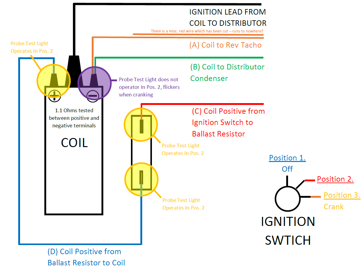
Overheating switch parked car heater 75. The coil gets a full momentary 12volts in the START position to give you a hotter spark during start ups. The second diagram shows two brake lights two indicators two side lights and a fog lightClick on the image below to enlarge itOther wiring diagrams on this site are listed below.
To solve the Run-On problem a Diode is supplied with the MSD in the parts bag. 915 857-2785 in the Pro Mag Tech department. These tachometers will usually have three wires and sometimes a fourth for a panel light.
I also went 12V and switched to negative ground. The Dyna S is completely housed behind the ignition cover and uses a magnetic rotor with the original spark advancer so the factory advance curve is maintained. 2003 Chevrolet Silverado Fuse Diagram for Underhood fuse box.
The diagram above shows a typical wiring schematic for aftermarket tachometers. Ballast resistor in heater 72. The 2N introduced in 1942 was the.
351 CLEVELAND BASICS AND PERFORMANCE TUNING FOR HIGH PERFORMANCE-STREET CARS AND SPORTS CARS During the 1960s Ford had manufactured small high winding V8 performance engines that demanded a lot from the driver and were some of the most expensive engines Ford manufactured. This is the same ignition used by top racers over the past 2 decades. Ballast resistors are common and cheap and come in typical sizes like 15 to 30 ohms.
46699 Ships Today FREE Shipping Lowest Price Guarantee. Switch Wiring DiagramFord 3000 Ignition Switch Wiring Diagram Ford WiringFord 4000 Ignition Switch Yesterday S Tractors Ford Tractor Ignition Switch Wiring Diagram Taesk Com May 1st 2018 - Ford Tractor Ignition Switch Wiring Diagram As Well As 123 Ignition Mounting Instructions Moreover Wired. First thought was wiring for a resistor for LED.
For Ford F-150 2010-2018. 2004 Chevrolet Silverado Fuse Diagram for Underhood fuse box. See diagram or call us.
Installing MSD Pro 600 Cam Sync on Small Block Ford. 7 way universal bypass relay wiring diagramSplit charge relay wiring diagramWiring in deck lights onto car hauler -. Such as with the Nissan GQ Patrol and Ford Maverick Kit wher e a flange on the distributor shaft needs to be.
The 6 volt coil will work but you need to swap the minus and plus sides and cut the voltage down from the 12 volts its now receiving. But you must install a Ballast Resistor Mallory 700 between the coil and the distributor install on Red wire coming out of the Unilite distributor. DDM Fuse PDM Fuse ECC Fuse AUX PWR 2 Fuse STUD 2 30A Trailer Wiring ABS 60A Electronic Brake Control Module EBCM.
View the appropriate diagram for complete wiring instructions. STUD 1 40A Trailer Wiring Automatic Level Control ALC Compressor Relay MBEC 1 50A SEAT CB. Seeds of chaos.
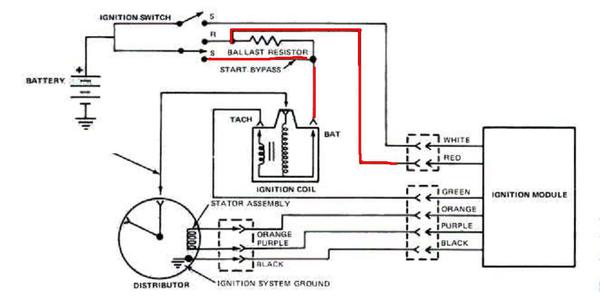
The wire running from the ignition switch to the coil will need to be cut and a ballast resistor put in line. 14 YELLOW - BYPASS LEG FROM STARTER I TERMINAL TO COIL THIS APPLIES MAX BATTERY VOLTAGE. 1964 mustang wiring diagrams.
Hull truth mid atlantic. An engine wiring diagram is provided in this section to help isolate electrical problems on. It has short circuit protection.
Early Ford and GM. If you use loom resistance wire connect to the coil terminal. This circuit is based on IC LM7812.
Ford 4000 Ignition Switch Yesterday S Tractors Ford Tractor Ignition Switch Wiring Diagram Taesk Com May 1st. If the vehicle has an intermittent fault at certain times or revs this is generally an engine problem and is not the fault of the ignitor. Thrower or in the form of a resistor wire or ballast resistor.
LED is a highly energy-efficient lighting technology and has the potential to fundamentally change. It was released in October 1939. Cycling the key may point to corroded or loose wires that have too much resistance and are getting hot.
It is a 3-terminal ve voltage regulator IC. 3 - My gut tells me to stay away from the 12 volt round can coils. Ford 3000 Ignition Switch Wiring Diagram Ford Wiring.
737 757 X465 M146737 M149118. If it is truly a 6-volt relay operating on a 12-volt system its no wonder the coil is blownBoth overvoltage and undervoltage are relay killers both causing high coil currents to be drawn eventually burning out the coil. 4l80e swap driveshaft length.
RT DOOR CB BLOWER 40A Blower Motor LBEC 2 50A LOCKS Fuse. 92995 6 Ships Today FREE Shipping. Wiring diagram ford starter mustang ignition solenoid 1964 relay switch 1994 1965 simplicity regent neutral throughout motorcycle motor f150 chevy.
We can then walk you through. Visually check for corrosion and tug at the wires on the connectors to make sure they are not loose or dirty. The pertronix ignitor is effectively a go or no system.
How To Wire Mid 1970s Through Mid 1980s Ignition Systems Retrofitting Electronic Ignition On Vehicles That Originally Had Points Allpar Forums

Century Resorter
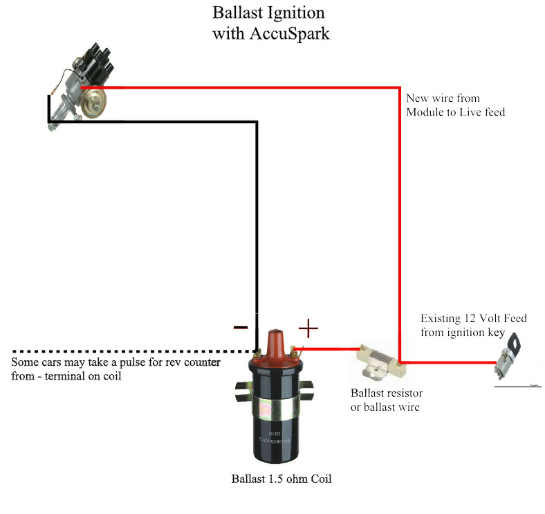
Accuspark Wiring Diagrams

Crane Xr7000 Wiring Diagram Tr7 Tr8 Forum The Triumph Experience
Mk2 Escort Cranking And Firing But Dies Straight Away Tech Talk Oldschool Co Nz

Duraspark Resistor The Ranger Station

Pertronix Electronic Ignition Installation For Ford Falcon Six Page No 1
Technical Differences In Ballast Resistors Help Me Get My Wheels Running Please The H A M B

Fordopedia Org
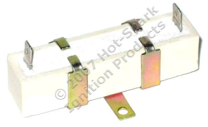
Heavy Duty External Ballast Resistor For Ignition Coils Points And Electronic Ignition Systems

Pertronix Relay Question Vintage Mustang Forums

Unique Simple Switch Wiring Diagram Wiringdiagram Diagramming Diagramm Visuals Visualisation Graphical Check More At Https Ignition Coil Wire Diagram

Electrical Wiring

Starter Solenoid Wiring Correctcraftfan Com Forums

Ignition Ballast Resistor On 1970 Mach1 Vintage Mustang Forums
![]()
Automotive History Electronic Ignition Losing The Points Part 1 Curbside Classic

Pertronix Installation Ford Lincoln And Mercury